

Circular IoT Design: A Practical Framework for Repairable, Upgradeable and Energy-Efficient Devices
Build IoT products engineered for repair, upgrade and long-term energy efficiency, with practical firmware and business blueprints.
Defining the Evergreen Challenge
Physical products age, break and consume energy. For Internet of Things devices this creates three intertwined, long-term problems: environmental impact from embedded materials and manufacturing, energy consumption during operation, and economic waste when devices become obsolete or unrepairable. These problems will persist regardless of current market cycles, so any durable strategy must address product design, software lifecycle, and business model together.
This briefing presents an integrated, evergreen framework for building IoT devices that are repairable, upgradeable and energy-efficient. It targets engineers, hardware teams, product managers and founders who need technical blueprints and sustainable business approaches that remain relevant for years. The content is practical and implementation focussed; it includes firmware patterns, hardware modularity guidelines and two business strategies with financial logic for circular models.
Why this matters, permanently
- Regulation and consumer expectation are moving toward producer responsibility for end-of-life devices; planning for take-back and repair will only grow in importance. See the UK government guidance on electrical and electronic equipment producer responsibility for formal context, here.
- Hardware supply chains and mineral scarcity create persistent cost and availability pressure; design for upgradeability reduces the need for full-device replacement.
- Energy consumption in millions of deployed devices compounds over time; designs that reduce operational energy save money and carbon across the product life.
Did You Know?
Design decisions at the point of product architecture, such as modular connectors and standardised bootloaders, can extend average device lifetime by multiple years with marginal up-front cost increases, transforming total lifecycle emissions and economics.
Scope and outcomes
After reading this briefing you will have:
- A clear hardware and firmware design checklist for repairable and upgradeable IoT devices.
- Concrete firmware patterns, including secure over-the-air (OTA) mechanisms and power-aware scheduling, with a substantial code example.
- Two proven circular business strategies: modular hardware platforms with component-level upgrade paths, and product-as-a-service with take-back and refurbishment flows, each with implementation steps and monetisation models.
- Operational guidance for manufacturing, logistics and end-of-life processing.
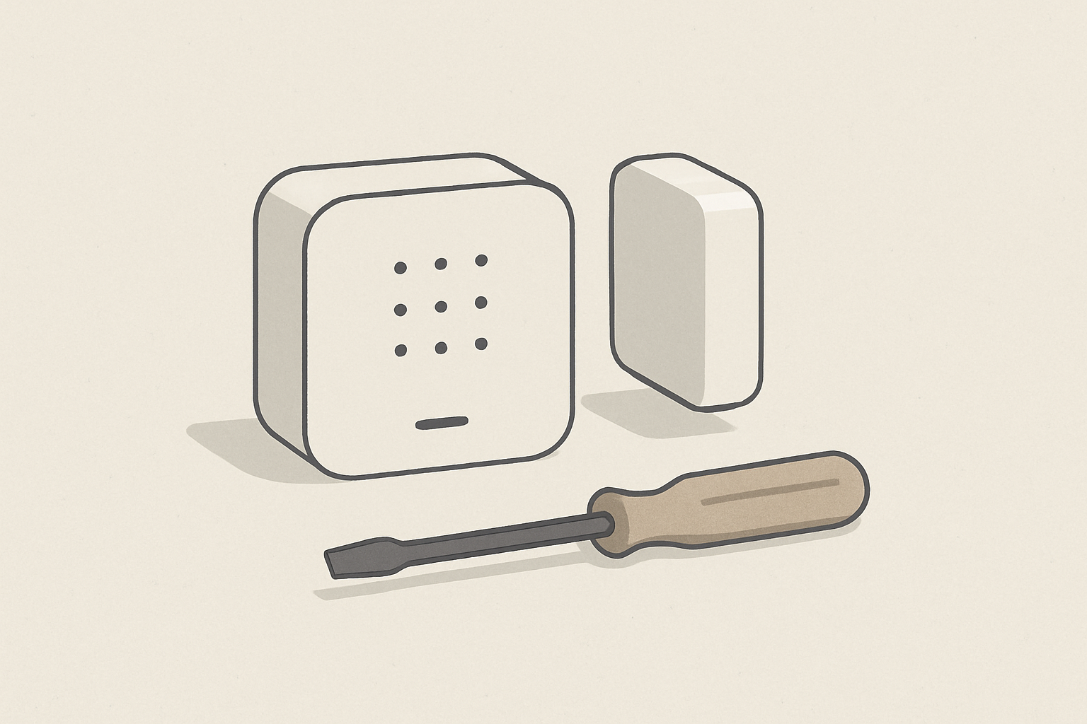
Solution A: Modular, repairable hardware platform
Concept
Design the device as a series of replaceable modules: power, radio/communications, compute, sensors, and user interface. Each module has a standard mechanical and electrical interface so modules can be replaced, upgraded or repaired independently. This is not niche; modularity is a long-lasting principle that balances manufacturability with serviceability.
Principles and rules
- Standard connectors and orientation, physically keyed to prevent incorrect insertion.
- Accessible fasteners and no epoxy; use captive screws and service clips where possible.
- Minimal custom parts; prefer off-the-shelf batteries, sensors and radios when they meet requirements.
- Clear labelling for module identification, including QR codes with part metadata and repair instructions.
- Design for disassembly: provide a clear, documented removal order and safe handling instructions for hazardous components like batteries.
Step-by-step implementation
- Define module boundaries based on failure rates and upgrade cadence. For example, radios tend to change with communication standards faster than power regulators. Prioritise modules that will most likely require service or upgrade.
- Draft mechanical interface: create a 2D template with hole patterns, alignment pins and a single connector family for power and data signals. Keep the connector pin count low for reliability.
- Standardise electrical signalling and power rails across modules; use a hot-plug tolerant power switching subcircuit to prevent brownouts during swaps.
- Design the enclosure for safe access; include service access points and a small, replaceable hatch for the battery compartment.
- Prototype with 3D-printed enclosures and revisioned PCB modules to validate fit and serviceability; iterate until removal and replacement takes under defined time thresholds for field service.
- Publish repair documentation and approved parts lists at product launch, including exploded diagrams and safety notes.
Manufacturing and supply-chain considerations
- Order modules in supply lots sized for multi-year service operations. Secure parts that are likely to see obsolescence and ensure substitute parts are qualified.
- Label components with UIDs at manufacture to enable traceability and predictive replacement.
- Design packaging and returns labels to facilitate reverse logistics for take-back or trade-ins.
Firmware and software patterns for repairable hardware
Repairable hardware becomes useful only when the software supports modular updates, device reconfiguration and secure restoration. The firmware should be modular, support independent revisioning per module, and allow secure rollback.
Key firmware features
- Unified bootloader that implements per-module authentication and recovery modes.
- Module-level firmware partitions with metadata for version and vendor.
- Secure OTA updates supporting delta patches and atomic swaps.
- Power-aware scheduling and network conservations to reduce operational energy.
Pro Tip: Implement a small recovery mode accessible via a hardware button and serial console; field technicians can reflash or validate modules without replacing the entire device.
Substantial code example: secure OTA and power-aware scheduling (ESP32, C, FreeRTOS)
The example below is deliberately practical and future-proof: it demonstrates a two-partition OTA scheme, per-module metadata checks, and a simple power-aware task scheduler. Use this pattern for any microcontroller that supports multiple flash partitions.
#include <stdio.h>
#include <string.h>
#include "esp_system.h"
#include "esp_ota_ops.h"
#include "nvs_flash.h"
#include "freertos/FreeRTOS.h"
#include "freertos/task.h"
// Simplified module metadata
typedef struct {
char module_name[16];
uint32_t version;
uint32_t checksum;
} module_meta_t;
// Simulate a function that verifies module signature
bool verify_module(const module_meta_t *meta) {
// In production, verify digital signature; here check checksum non-zero
return (meta && meta->checksum != 0);
}
// Simple power-aware sleep wrapper
void power_aware_sleep(uint32_t millis) {
// On battery-powered devices, adjust sleep duration to save energy
// For example, if battery < 20% increase sleep interval (pseudocode)
// battery_pct = read_battery_percent(); if (battery_pct < 20) millis *= 4;
vTaskDelay(pdMS_TO_TICKS(millis));
}
void ota_update_task(void *pvParameters) {
// Check for available updates for each module
module_meta_t new_meta;
// In practice, get metadata from secure server over TLS
while (1) {
// Placeholder: fetch module update info
if (/* server_has_update() */ false) {
// Download delta, write to inactive partition
// esp_ota_begin, esp_ota_write, esp_ota_end
// Verify image
if (verify_module(&new_meta)) {
// Mark partition bootable
// esp_ota_set_boot_partition(new_partition);
}
}
power_aware_sleep(60000); // check every 60s, adjust based on battery
}
}
void app_main() {
nvs_flash_init();
// Start OTA task
xTaskCreate(&ota_update_task, "ota_task", 4096, NULL, 5, NULL);
// Main loop: device operation
while (1) {
// Perform sensing, local processing
power_aware_sleep(10000); // normal operating sleep
}
}
Notes on the example
- Replace the placeholder verification with digital signature validation, for example using ECDSA and a device-unique key.
- Implement delta patching to reduce bandwidth and energy during updates.
- Partitioning: keep module firmware data in separate partitions or use a file-system layout that allows swapping only the relevant module binary.
OTA security checklist
- Supply chain signing keys, hardware root-of-trust or secure element for key storage.
- Signed manifests with per-module hashes and version constraints.
- Rollback protection and safe boot with a validated fallback partition.
- Rate limits and verification to avoid bricking devices on intermittent networks.
Solution B: Circular business models for longevity
Technical design must be paired with business models that incentivise repair and reuse. Two evergreen models scale well across industries: modular upgrade pathways with spare parts marketplaces, and product-as-a-service with take-back and refurbishment loops.
Model 1: Modular upgrade marketplace
Overview: sell a base device with replaceable modules. Offer certified upgrade modules for new radios, sensors, or compute upgrades. Create a marketplace for certified third-party modules to stimulate an ecosystem.
Implementation steps
- Define upgrade tiers and compatible module interfaces; publish technical interface control documents (ICDs).
- Build a certification programme for third-party module vendors including test suites and security requirements.
- Provide an online marketplace with part numbers, revision history and firmware compatibility tables.
- Price modules to make upgrades more attractive than entire device replacement.
- Offer exchange credits for returned modules to feed refurbishment operations.
Monetisation and financial logic
Revenue comes from module sales, certification fees and platform transaction fees. The model reduces churn while creating recurring revenue from upgrades. Unit economics improve because the company retains the core device ownership longer, reducing lifetime acquisition costs per customer.
Model 2: Product-as-a-service and refurbishment loop
Overview: retain ownership of hardware, lease devices to customers with a subscription that includes maintenance, upgrades and end-of-life handling. At contract end, devices are returned, inspected, refurbished and redeployed.
Implementation steps
- Estimate mean time between failure (MTBF) and refurbishment yield using prototypes and pilot programmes.
- Set subscription pricing to cover amortised hardware cost, expected refurbishment cost and margin. Include an expected reuse multiplier, for example plan to redeploy each device 2.5 times on average.
- Set up a certified refurbishment facility with test benches, battery replacement workflows and secure data erasure processes.
- Implement logistics for returns, including prepaid returns labels and regional collection points.
- Provide customers with clear SLAs for uptime and replacement devices while refurbishments occur.
Monetisation and financial logic
Leasing converts capital expenditure into predictable recurring revenue. Refurbishment improves gross margin because a refurbished device costs significantly less than a new build, and customer lifetime value increases as devices remain in service longer. Model stress tests should include failure rates, refurbishment yield and logistics cost sensitivity.
Q&A: Can small companies afford refurbishment centres? Yes, start with a single regional bench and partner with third-party refurbishers; the objective is validated processes, not immediate scale.
Operationalising take-back and end-of-life
Handling returns requires compliance, safety controls and efficient processing.
Key guidelines
- Segregate returned items into categories: refurbishable, parts-harvestable, recycling-only, hazardous waste.
- Implement a fast diagnostic workflow with barcode scanning and automated test benches to triage returns within minutes.
- Store and process batteries in appropriate conditions; forward end-of-life or non-recoverable batteries to approved recyclers.
- Maintain accurate inventory of harvested parts for reuse and maintain provenance records for safety and warranty.
For UK-specific regulatory context on producer responsibility for electrical equipment, consult the official guidance on the WEEE scheme at the UK government site, here.
Comparing the two solutions
Both solutions aim to lengthen product lifetime and reduce environmental impact, but they differ in risk profile and revenue dynamics.
- Modular upgrade marketplace has lower operational overhead at launch, and it scales by engaging ecosystem partners. Revenue is product and transaction-based; complexity centres on interface stability and certification governance.
- Product-as-a-service requires higher operational capability upfront, with logistics and refurbishment infrastructure, but yields steadier recurring revenue and tighter lifecycle control. It is capital intensive but can offer superior lifecycle emissions reduction because the operator controls repair and reuse.
Implementation checklist for engineering teams
- Define module boundaries and create interface control documents.
- Design enclosures and mechanicals for disassembly and safe battery access.
- Implement a secure, partitioned firmware architecture with verified OTA and rollback capability; use hardware-backed keys where feasible.
- Publish repair documentation and spare parts lists at launch.
- Plan supply-chain buffers for parts likely to see obsolescence.
- Design logistics and return packaging at the same time as mass production planning.
Governance, standards and third-party verification
Adopt recognised standards and verify claims through third-party testing. Consider:
- CE marking and radio compliance as required.
- Battery safety and transport regulations.
- Independent refurbishment certification and data-wiping verification.
Cross-cutting technical patterns
- Use semantic versioning for module firmware and explicit compatibility matrices.
- Prefer localised, incremental updates (delta patching) to minimise bandwidth and energy costs.
- Instrument devices with telemetry that measures energy consumption and failure modes, keeping privacy and minimal data collection principles intact.
Did You Know?
Local processing to reduce network round-trips can save more energy across a fleet than marginal hardware efficiency improvements, because fewer radios are active and the device can spend more time in low-power sleep states.
Case study blueprint: 10-step pilot to validate circular IoT
- Define pilot scope: region, number of devices and target customer segment.
- Design base hardware and one upgradeable module for the pilot.
- Build a prototype with accessible service points and create repair documentation.
- Implement firmware with signed OTA and recovery mode; integrate simple telemetry for battery and error logging.
- Select logistics partner for returns and set up a small refurbishment bench.
- Run a small pilot (50-200 devices) for 6 to 12 months and measure MTBF, refurbishment yield and customer satisfaction.
- Analyse economics and iterate on module pricing and subscription levels.
- Publish transparent sustainability metrics for the pilot, including reuse rates and refurbish yield.
- Refine processes and scale to larger cohorts, adding third-party module vendors if using the marketplace model.
- Transition to regionally distributed refurbishment hubs as volumes justify.
Long-term considerations and risk management
- Plan for interface stability; breaking module interfaces will fragment the ecosystem.
- Mitigate supply risk by qualifying alternate suppliers and designing for part substitution.
- Protect firmware signing keys and rotate keys according to a documented key-management lifecycle.
Warning: Over-modularising a product can increase single-point failures through connector wear; balance modularity with durability testing and connector lifecycle validation.
How this complements software-focused sustainability
Hardware circularity works best when combined with low-carbon software practices. For teams working with data and machine learning, see the technical framing in 'Low-Carbon Data and ML: An Engineer's Framework for Sustainable Pipelines and Models' for strategies on reducing operational carbon through software design and efficient pipelines, which apply equally to device-side processing and cloud components, Low-Carbon Data and ML: An Engineer's Framework for Sustainable Pipelines and Models.
Evening Actionables
- Download and publish an interface control document (ICD) template for your next device; include mechanical, electrical and firmware partition details.
- Implement a minimal OTA bootloader with partitioned firmware and rollback support; use the code pattern in this briefing as a starting point.
- Run a 3-month pilot with 50 devices to validate repair time targets and refurbishment yield; measure MTBF and energy consumption telemetry.
- Create a take-back plan and identify at least one certified recycler for batteries.
- Decide on a circular business model to pilot, either modular marketplace or product-as-a-service, and draft a 12-month P&L that includes refurbishment costs and reuse assumptions.
Designing for repairability, upgradeability and energy-efficiency is a long-term investment that aligns product durability with customer value and regulatory direction. The frameworks in this briefing provide a durable roadmap for teams building the next generation of sustainable IoT products.


Comments ()